Home » Without Label » 6 Lead 480V Motor Wiring - Image result for 3 phase motor terminals | Electrical ... / Usa u5 v5 w5 l1 l2 l3 u2 v2 w2 t6 t1 t2 t3 t4 t5 u1 v1 w1 t7 t8 t9 u5 v5 w5 motor connection diagrams uscs 0100.
6 Lead 480V Motor Wiring - Image result for 3 phase motor terminals | Electrical ... / Usa u5 v5 w5 l1 l2 l3 u2 v2 w2 t6 t1 t2 t3 t4 t5 u1 v1 w1 t7 t8 t9 u5 v5 w5 motor connection diagrams uscs 0100.
6 Lead 480V Motor Wiring - Image result for 3 phase motor terminals | Electrical ... / Usa u5 v5 w5 l1 l2 l3 u2 v2 w2 t6 t1 t2 t3 t4 t5 u1 v1 w1 t7 t8 t9 u5 v5 w5 motor connection diagrams uscs 0100.. Otherwise, the arrangement will not work as it ought to be. Sound like a smart a$$, but this is important} if you get to the stage whereby a voltage is produced, then mark the b wire at the junction with c as b1. 3 phase motor wiring diagram 12 leads. There are 2 standard ways to correctly wire a 6 lead motor. T1+t6+t7+t12 t2+t4+t8+t10 t3+t5+t9+t 12 lead.
This is a 12 lead motor not a 9 lead motor. Follow the book every time. The six leads are numbered 1,2,3,6,7,8 or it's 1,2,3,7,8,9. I have a 277480 volt panel. This special motors have 6 wires and depending of the connection could run at high or low speed at only one voltage, in your case the high speed is 3550 and the low is 1770 rpm.
6 Lead 3 Phase Motor Wiring Diagram 6 Wire - Wiring ... from lh3.googleusercontent.com For specific leeson motor connections go to their website and input the leeson catalog # in the review box, you will find connection data, dimensions, name plate data, etc. The 6 leads are what's throwing me. Most use the high voltage wiring diagram only. The six leads are numbered 1,2,3,6,7,8 or it's 1,2,3,7,8,9. Motor wiring diagram installation maintenance manual abb baldor em4316t 12 75hp 1780rpm connecting motors for a change of voltage 460 volt 3 phase 6 lead how to wire 13 three diagrams 230v madcomics single nine on w cutler hammer drum switch rotary converter create 480 1hp 5hp practical machinist largest sawmill creek woodworking community and operating wye. There are 2 standard ways to correctly wire a 6 lead motor. 6 lead 480v motor wiring | l1 is wired to motor 1terminal t1, l2 2 is wired to3 motor termin4al t2, and l35 is wired to m6 otor termina7l t3. Usa u5 v5 w5 l1 l2 l3 u2 v2 w2 t6 t1 t2 t3 t4 t5 u1 v1 w1 t7 t8 t9 u5 v5 w5 motor connection diagrams uscs 0100.
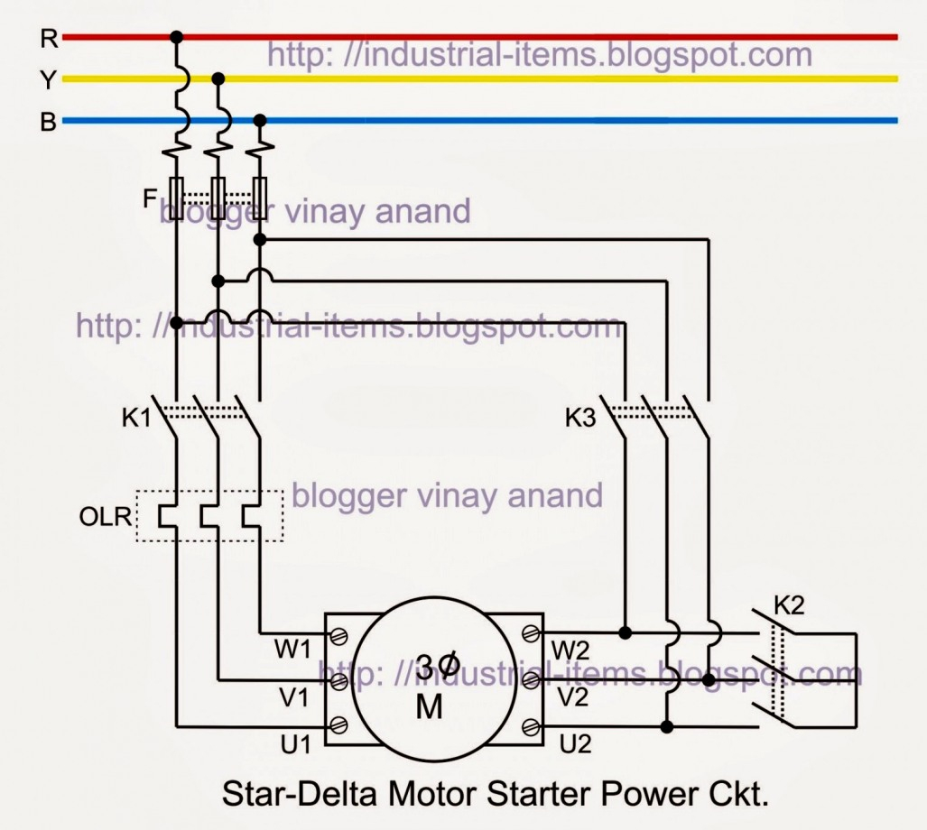
6 lead 480v motor wiring | electrical motors 12 lead, dual voltage, wye start/delta run, both voltages or 6 lead, single voltage, wye start/delta run motors designed by us motors for wye start, delta run may also be used for across the line starting using only the delta connection.
Electrical motors 12 lead, dual voltage, wye start/delta run, both voltages or 6 lead, single voltage, wye start/delta run motors designed by us motors for wye start, delta run may also be used for across the line starting using only the delta connection. Follow the book every time. 4 inch (10cm) long black and red wire leads already soldered for easy connection to your circuit. On the motor there is a low voltage wiring and a high voltage wiring. There are about two dozen ways to wire it up total. The delta connection is for the low voltage. It was previously fed with 480, when it was move instead of leaving the split bolts and cutting the feeders they cut the leads instead. The six leads are numbered 1,2,3,6,7,8 or it's 1,2,3,7,8,9. The above name plate belongs to one single winding/two speed motor. 230v 3 phase motor wiring madcomics. Always use wiring diagram supplied on motor nameplate. If it's zero or reads some continuity at all, then a problem is present with the motor or cable. On machines rated for two voltages, the wye connection is for the high voltage;
230v 3 phase motor wiring madcomics. This special motors have 6 wires and depending of the connection could run at high or low speed at only one voltage, in your case the high speed is 3550 and the low is 1770 rpm. There are 2 standard ways to correctly wire a 6 lead motor. Disconnect all power from the system. This is a 12 lead motor not a 9 lead motor.
3 Phase 6 Lead Motor Wiring Diagram | Wiring Diagram from annawiringdiagram.com In either case, you first have to figure out which leads are pairs as charles described. T1+t6+t7+t12 t2+t4+t8+t10 t3+t5+t9+t 12 lead. Some work, some do nothing, some destroy it. 3 phase motor winding resistance values, using ohm meter: 3 phase motor wiring diagram 12 leads. 6 lead 480v motor wiring | electrical motors 12 lead, dual voltage, wye start/delta run, both voltages or 6 lead, single voltage, wye start/delta run motors designed by us motors for wye start, delta run may also be used for across the line starting using only the delta connection. Follow the book every time. Mark the c wire at the multimeter as c1.
A three phase motor is more efficient than a single phase motor because of the peculiarities of alternating current ac.
Identifying the windings in a six lead motor. The second suffixing letter f or h denotes insulation class. 480 volt motor wiring diagram. This reduces the wire cost and often simplifies manufacturing. Although it looks like a dayton it is made by relay and. And the main voltage is 480 v. Check all three wires singly t1, t2, t3 (three phases) to the ground wire. Coils ii, iii, and iv are permanently connected and cannot be separated. This video is brought to you by: Those nine leads provide an option for supplying power from either high or low voltage sources. 480 volt 3 phase 6 lead wiring diagram disclaimer. On machines rated for two voltages, the wye connection is for the high voltage; Industry wide the 480 volt 3 phase motor is the most common of all.
I have a 277480 volt panel. The second suffixing letter f or h denotes insulation class. A three phase motor is more efficient than a single phase motor because of the peculiarities of alternating current ac. 480 volt motor wiring diagram. The six leads are numbered 1,2,3,6,7,8 or it's 1,2,3,7,8,9.
480V 3 Phase 6 Lead Motor Wiring Diagram Collection from waterheatertimer.org Always use wiring diagram supplied on motor nameplate. This video will show you how to wire up a 9 wire 3 phase motor to a 480 volt system.watch till the end for my tech tip.if performing on site, be sure to powe. I have to hook up a 50hp 480v motor, the schematic is gone. This reduces the wire cost and often simplifies manufacturing. This video is brought to you by: Coils ii, iii, and iv are permanently connected and cannot be separated. 480 volt motor wiring diagram. The above name plate belongs to one single winding/two speed motor.
And the main voltage is 480 v.
This is a 12 lead motor not a 9 lead motor. This will give you the relationship between the b and c wires. 480 volt motor wiring diagram. Electrical motors 12 lead, dual voltage, wye start/delta run, both voltages or 6 lead, single voltage, wye start/delta run motors designed by us motors for wye start, delta run may also be used for across the line starting using only the delta connection. Here is a sample wiring diagram: On six lead single voltage motors watch out and check the manufacturer diagrams. T1+t6+t7+t12 t2+t4+t8+t10 t3+t5+t9+t 12 lead. Identifying the windings in a six lead motor. A three phase motor is more efficient than a single phase motor because of the peculiarities of alternating current ac. 480 volt 3 phase 6 lead wiring diagram disclaimer. Sound like a smart a$$, but this is important} if you get to the stage whereby a voltage is produced, then mark the b wire at the junction with c as b1. The second suffixing letter f or h denotes insulation class. Otherwise, the arrangement will not work as it ought to be.